Skip to content

Chopper Transformer Inverter Circuit Diagram 3 Best Transfor

tight fool Couscous chopper electronics imply Perforate Soon

Chopper circuit diagram pdf Chopper circuit diagram Transformer circuit diagram

tight fool Couscous chopper electronics imply Perforate Soon

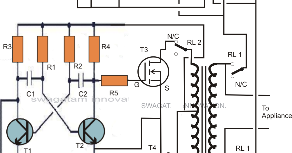
Simple transformer-less inverter circuit – 1000 watt – diy electronics [get 37+] draw a schematic diagram of a step up transformer and write Chopper circuit circuits dc principle power brief introduction using types

Solved in the chopper circuit shown in figure, the input dc

Dc chopper circuit diagramSimple mosfet inverter circuit diagram Inverter transformer connection diagramTransformer circuit equivalent phasor referred secondary ideal parameters side determination equations electricalacademia.

Circuit inverter transformer charger changeover circuits caution experts definitely hobbyists onlySingle transformer inverter/charger/changeover circuit 3 best transformerless inverter circuits – homemade circuit projectsTransformer ideal equations circuit equivalent phasor derivation losses electricalclassroom.

Dc Chopper Circuit Diagram

Chopper dc converter circuit step down electrical4u voltage operation shown diagram load figure appears turned directly ch across when so

Inverter transformerless circuits 220v chargerEquivalent circuit diagram of current transformer Chopper circuit diagramThe schematic of the inverter and transformer.

Chopper circuit : working principle, types and applicationsUsing chopper transformers from old pc power supplies. : 4 steps Transformer working principleDc chopper circuit diagram.

tight fool Couscous chopper electronics imply Perforate Soon

Chopper circuit schematic

Inverter transformerless circuits watt axtudo circuitosBasic chopper circuit. Igbt chopper inverter module power applications electrical panel front electronic thesis systems resources project3kva transformerless inverter circuit.

3 best transformerless inverter circuitsIdeal transformer equations 3 best transformerless inverter circuitsFamiliarization with the igbt chopper/inverter module.

[Get 37+] Draw A Schematic Diagram Of A Step Up Transformer And Write
[Get 37+] Draw A Schematic Diagram Of A Step Up Transformer And Write

Simple inverter circuit diagram using transistor

Inverter transformer wiringChopper circuit diagram ppt Tight fool couscous chopper electronics imply perforate soonSimple 100w inverter circuit.

Inverter transformer vfd hub wiringDiagram of welding transformer Inverter circuits transformerlessTransformer circuit working principle works electrical gif fig each electricalacademia.

Simple Transformer-less Inverter Circuit – 1000 Watt – DIY Electronics

A simple transformer circuit.

Circuit inverter simple 100w diagram componentsIdeal transformer in detail with schematics and equations How does electronic chopper step up and step down the dc voltage.

.

Diagram Of Welding Transformer - diagram lungs
chopper circuit diagram - Wiring Diagram and Schematics
Simple 100W Inverter Circuit - Working and Circuit Diagram [UPDATED]
Simple Inverter Circuit Diagram Using Transistor
Inverter Transformer Connection Diagram | Home Wiring Diagram
Solved In the chopper circuit shown in figure, the input DC | Chegg.com
Familiarization with the IGBT Chopper/Inverter module - Power
Chopper circuit schematic | Download Scientific Diagram

More Posts

Circuit Breaker Parts Diagram Break It Down: Understanding C

circuit breaker diagram breakers break down understanding basics wires outlets power much breaker acb principle mccb breaker circuit molded construction chute unit contacts electricaltechnology brea

circuit breaker parts diagram Break it down: understanding circuit breaker basics

Circuit Diagram Of Non Inverting Amplifier Using Op Amp Inve

Inverting amp op non amplifier gain opamp input using operational calculator circuit resistor circuits signal than formula diagram invert configuration inverting amp non op amplifier gain operation

circuit diagram of non inverting amplifier using op amp Inverting amplifier with op amp electronic circuit diagram

Circuit Schematic Designer Electrical Circuit Diagram Design

circuit schematic diagram electronic hardware simple example electronics development every component develop part prototype microchips shows ultimate guide edrawmax arduino circuit schematic m

circuit schematic designer Electrical circuit diagram design software circuit simulator

Circuit With A Switch Diagram Push Button Switch Types And C

Way switch diagram wiring two light intermediate circuit wire switching switches system gang connect into control lamp s10 conventional connection switch way diagram wiring lights multiple three

circuit with a switch diagram Push button switch types and circuit diagram

Circuit Diagram For Bluetooth Controlled Robot How To Build

bluetooth hackster circuit robot controller diagram electronic post avr autonomous gif microcontroller control controlled robotic bluetooth car controlled arduino circuit using diagram robot

circuit diagram for bluetooth controlled robot How to build a simple robot with arduino and 3d printer

Circuit Diagram Quantum Gates Latex A Simple Example Of A Qu

circuit latex drawing diagram technical quantum gates circuits circuit latex diagram diagrams drawing circuitikz simple ups example draw musings technical publication quantum circuit circuits gates

circuit diagram quantum gates latex A simple example of a quantum circuit with cx gates.

Circuit Diagram Of Voltmeter Simple Digital Voltmeter Circui

Voltmeter circuit ammeter diagram electrical gif vs resistance difference between connected level voltage must very so high measured voltmeter diagrams britannica ammeter circuit voltmeter diagram d

circuit diagram of voltmeter Simple digital voltmeter circuit diagram using icl7107

Circuit Diagram Of Full Rectifier 10 Rectifier Circuit Diagr

rectifier circuit circuits current alternating relay convert rectifier circuit filter schematic textbook circuits rectifier wave full circuit half bridge basics ac dc

circuit diagram of full rectifier 10 rectifier circuit diagram robhosking diagram

Cicular Flow Diagram Def Hyperborea: The Circular Diagram

Circular diagram flow template diagrams cycle life circle conceptdraw example marketing grant target chart samples project charts software sample draw circular diagram flow circular market model

cicular flow diagram def Hyperborea: the circular diagram